Understanding the PC field on RFID Tags
Interested in understanding the inner workings of RFID tags, particularly the "PC" or "Protocol Control" bits? In this post, we'll delve into what the PC field represents, how to decode it, and how RFIDLinked can streamline the decoding process for you.
Simplifying PC Decoding with RFIDLinked
Before we dive into the technical details, RFIDLinked makes understanding these values a breeze as it automatically decodes PC values for you. Plus, our web application features a handy PC value decoder, allowing you to input the hexadecimal value and extract the information in a snap.
What is the PC Memory Field?
RFID Tag Memory Map
Let's start with the basics. The PC, or Protocol Control bits, is a crucial segment of memory within RFID tags. Specifically, it's housed in Bank 1, also known as the EPC bank. But what does it do? In short, the PC field describes the physical characteristics of the RFID tag, including details such as how much memory is available for storage in the EPC and User memory banks, and additional metadata about the item being tagged.
Breaking Down the PC Bits
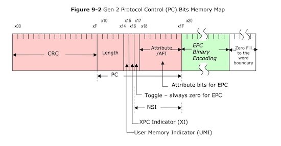
PC Memory Map
The PC field begins at bit position 10h, and are divided into six separate fields. Use the diagram to map each bit position to the field descriptions below.
Length bit positions 10h - 14h
The first 5 bits represent the size of the EPC memory bank. The value encodes how many “words” the EPC memory bank contains. A word is defined as 16 bits. So take this value and multiple it by 16 to calculate the total number of bits for the EPC value.
| Binary Value | Hex Value | Number of Words | Number of Bits |
|---|---|---|---|
00000b |
0h |
0 | 0 bits |
00001b |
1h |
1 | 16 bits |
00010b |
2h |
2 | 32 bits |
00011b |
3h |
3 | 48 bits |
00100b |
4h |
4 | 64 bits |
00101b |
5h |
5 | 80 bits |
00110b |
6h |
6 | 96 bits |
00111b |
7h |
7 | 112 bits |
01000b |
8h |
8 | 128 bits |
User Memory Indicator (UMI) bit position 15h
This bit is used to indicate if the User memory bank is present and contains data on the tag.
For example, if the tag does NOT contain a user memory bank, or the user memory bank is NOT programmed with any data, the value of this bit will be 0.
Conversely, if the tag DOES contain a user memory bank and it has been programmed with data, the value of this bit will be 1.
XPC Indicator (XI) bit position 16h
This bit is used to indicate if the XPC block of memory exists on the tag. The XPC bits are the “Extended Control bits”.
Toggle Bit: bit position 17h
This bit is used to indicate how the remaining 8 bits of the PC field is encoded.
A value of 1 means that the remaining 8 bits (position 8 - 15) are encoded as Attribute bits (see decoding below).
A value of 0 means that the remaining 8 bits (position 8 - 15) are encoded as an Application Family Identifier (see decoding below).
Attribute Bits bit positions 18h - 1Fh
If the Toggle bit at position 17h has a value of 1, then these 8 bits represent additional attributes or information about the physical object the RFID tag is affixed to. It’s important to note that these attribute bits are not intended to provide any identity information about the product, that information is encoded within the EPC field.
As of May of 2024, there is only one value contained within the specification at bit position 1Fh.
| Bit Position | Meaning |
|---|---|
| 18h | - no meaning assigned - |
| 19h | - no meaning assigned - |
| 1Ah | - no meaning assigned - |
| 1Bh | - no meaning assigned - |
| 1Ch | - no meaning assigned - |
| 1Dh | - no meaning assigned - |
| 1Eh | - no meaning assigned - |
| 1Fh | A value of 1 in this position indicates that the item tagged is a hazardous material. |
AFI Bits: bit positions 18h - 1Fh
If the Toggle bit at position 17h has a value of 0, then these 8 bits define who assigned the tag, with specific values assigned to various entities. These values can be decoded as follows:
| Value in Binary | Value in Hex | Assigning Entity |
|---|---|---|
| 00000000b | 00h | Unassigned |
| 00000001b | 01h | Self Assigned 1 |
| 00000010b | 02h | Self Assigned 2 |
| 00000011b | 03h | Self Assigned 3 |
| 00000100b | 04h | Assigned by Tag Mfr |
| 00000101b | 05h | Assigned by Transport Company |
| 00000110b | 06h | Assigned by End User |
| 00000111b | 07h | Control of Recirculating Items |
Wrap Up
In conclusion, the PC memory field plays a vital role in the physical properties, origin, and identification of RFID tags. With RFIDLinked, decoding these values becomes effortless, empowering you to harness the full potential of RFID technology.
Sources
ISO15961


